Steady Method Thermal Conductivity Measurement System
GH series
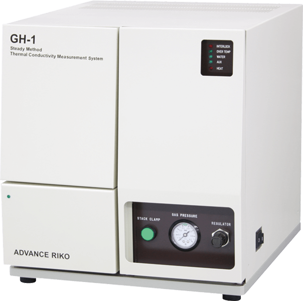
Thermal conductivity evaluations of polymers and glass
A heat-flow method Steady Method Thermal Conductivity Measurement System that complies with the US ASTM E1530 standard.
This system measures comparatively low-thermal conductivity materials over a temperature range of 50 to 280°C.
Applications
- Thermal conductivity evaluations of semiconductor package materials.
- Thermal conductivity evaluations of glass substrates.
- Thermal conductivity evaluations of polymer materials.
- Thermal conductivity evaluations of ceramic materials.
- Thermal conductivity evaluations of low-thermal conductivity metals.
- Thermal conduction measurements of thermoelectric materials.
Features
- Designed to minimize heat loss in the surface direction with the guard heater.
- Automatic measurement
Automatic measurement between 50-300ºC can be possible by only inputting measurement temperature into PC. - Accurate measurement
Calibration data of 304 Stainless Steel, Pyrex, and Vespel have been registered in advance.
Thermal conductivity of unknown materials can be calculated by the comparison of the calibration data. - Sufficient monitor display
Temperature and thermal conductivity (reference value) of each part of sample holder can be displayed during the measurement. - Capable of measuring film (Option).
Thermal conductivity of relatively low thermal conductivity materials such as thin sheet and film samples can be measured by stacking method.
Specifications
| Temperature range | 50 ~ 280 °C |
|---|---|
| Sample size | ➀ □ 25 × t 1.5 ~ 8 (mm) ➁ φ 25 × t 1.5 ~ 8 (mm) ➂ □ 50 × t 1.5 ~ 12 (mm) ➃ φ 50 × t 1.5 ~ 12 (mm) |
| Measurement range | Sample size ➀ ➁ 0.1~15Wm-1K-1 Sample siz e➂ ➃ 0.1~20Wm-1K-1 |
| Atmosphere | Air |
Measurement principle diagram
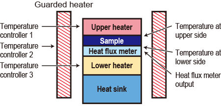
Calculation formula of thermal resistance

Rs:Thermal resistance of sample
N :Proportional coefficient
TL:Lower side temperature of sample
Tu:Upper side temperature of sample
Q :Heat flux meter output
Ro:Contact thermal resistance of upper and lower interface
By using N calculated from calibration sample, thermal resistance of sample, Rs, is found by the above equation. Thermal conductivity, λ, is given by N substituting Rs into the following equation.

λ:Thermal conductivity of sample
d:Sample thickness
Screen for setting and measurement
*The software is actually Englush version.
Screen for inputting sample conditions.
Screen for measurement.
Screen for displaying date grafh.
A patent and a standard
US standard ASTM E1530Analysis service by using this product
Related product
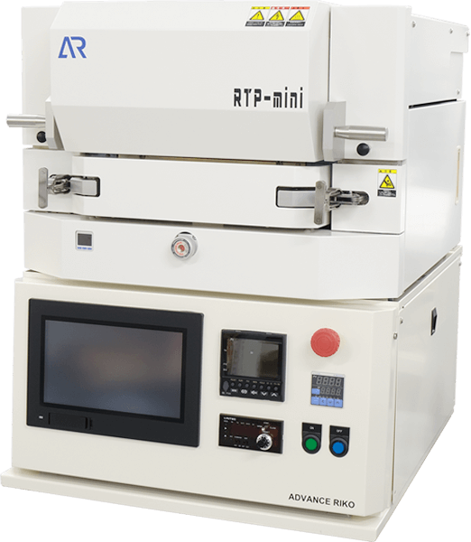
Infrared lamp heating system RTP-mini
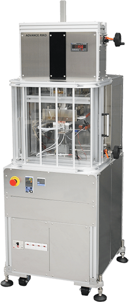
Thermal Flow Rate Evaluation System for Low Thermal Resistance Multilayer Substrates F-CAL
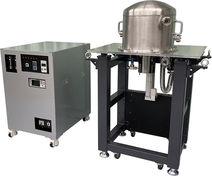
Ultra High Precision Thermal Expansion Measurement System by Laser Interferometer SuperLIX
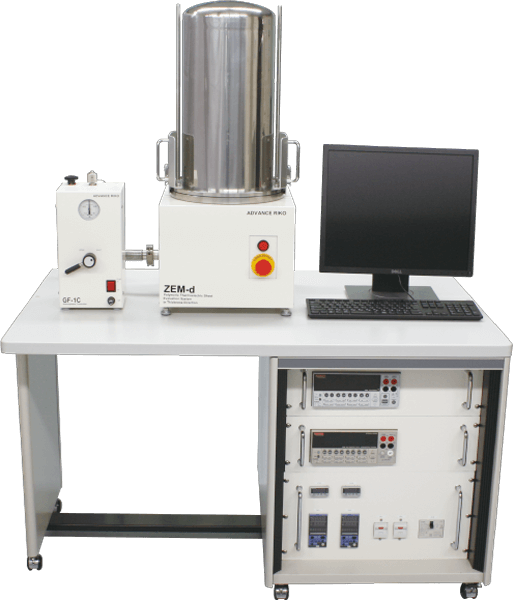
Polymeric Thermoelectric Sheet Evaluation System ZEM-d
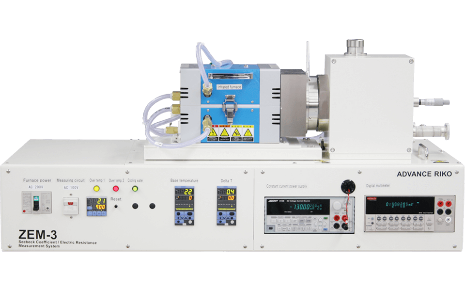
Seebeck Coefficient / Electric Resistance Measurement System ZEM-3 series

Atmospheric Thermoelectric Module Evaluation System F-PEM
Steady Method Thermal Conductivity Measurement System GH series Contact form
The information that you enter will only be used to provide you with a response. However, when you request that we mail you a catalog or other materials, please understand that the shipper specified by ADVANCE RIKO may use only the information necessary to send those materials, such as your name and address.
Please check our privacy policy for more details.