Seebeck Coefficient / Electric Resistance Measurement System
ZEM-3 series
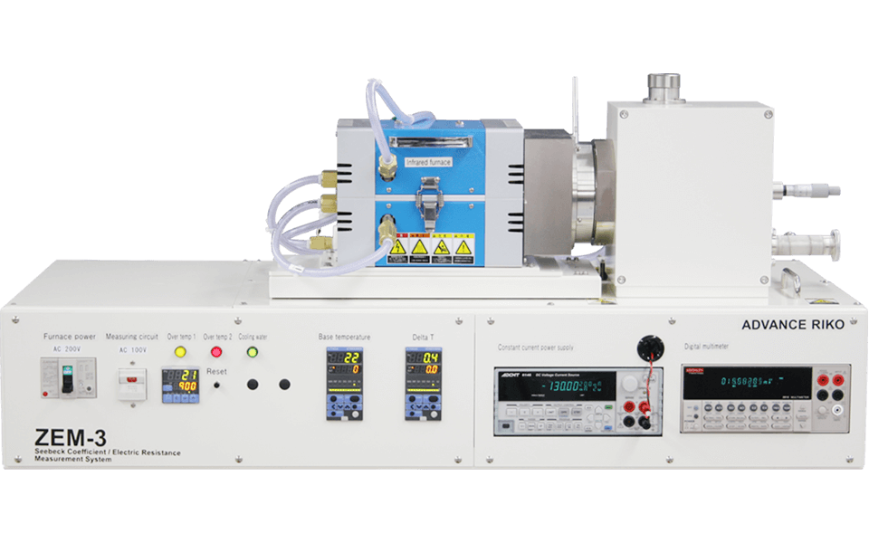
Simultaneously measures the Seebeck coefficient and electric conductivity of thermoelectric materials.
Based on requests from both domestic and international academic societies and customers, this system features our easy to use, high-precision measurement techniques.
Complies with JIS standards for thermoelectric material Seebeck coefficient measurement equipment.
Applications
Evaluate the thermoelectric properties of a wide variety of materials including semiconductors, ceramics, and metalsFeatures
- A Infrared Gold Image Furnace with excellent temperature controllability and a micro-heater for temperature difference control
- The measurements are controlled by a computer and enable to perform the measurements at specified temperatures on each emperature difference which eliminates dark electromotive force and allows automatic measurements
- Ohmic contact automatic check function (V-I plot) as a standard function
- Available to measure a thin film with an original adapter as an option.
- Customizable to high resistance type
Specifications
| Model | ZEM-3L | ZEM-3LW | ZEM-3M8 | ZEM-3M10 |
|---|---|---|---|---|
| Temperature Range | -80 °C to 100 °C | -100 °C to 200 °C | RT, 50 °C to 800 °C | RT, 50 °C to 1000 °C |
| Measurement Properties | Seebeck coefficient, electric resistivity | |||
| Sample Size | 2 to 4 mm square or φ x 5 to 22 mm length | |||
| Measurement Atomosphere | Low-pressure He gas | |||
| Optional | Cooling water circulator Thermoelectric generation simulation software Thin film attachment Measurements in various atmospheres (negotialble) |
|||
Measurement principle
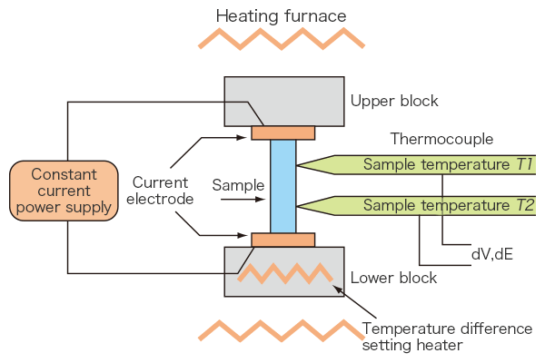
A prism or cylindrical sample is set in a vertical position between the upper and lower blocks in the heating furnace. While the sample is heated, and held, at a specified temperature, it is heated by the heater in the lower block to provide a temperature gradient. Seebeck coefficient is measured by measuring the upper and lower temperatures T1 and T2 with the thermocouples pressed against the side of the sample, followed by measurement of thermal electromotive force dE between the same wires on one side of the thermocouple.
Electric resistance is measured by the dc four-terminal method, in which a constant current I is applied to both ends of the sample to measure and determine voltage drop dV between the same wires of the thermocouple by subtracting the thermo-electromotive force between leads.
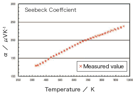
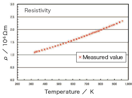
Measurement Example of P Type Si80Ge20 Sintered Compact
Application
One-Minute Joule Annealing Enhances the Thermoelectric Properties of Carbon Nanotube Yarns via the Formation of Graphene at the Interface
ACS Appl. Energy Mater. 2019, 2, 7700-7708
DOI : 10.1021/acsaem.9b01736
Fabrication by Coaxial-Type Vacuum Arc Evaporation Method and Characterization of Bismuth Telluride Thin Films
M. UCHINO,1 K. KATO,2 H. HAGINO,1 and K. MIYAZAKI1,3
Journal of ELECTRONIC MATERIALS, 2013 TMS
DOI : https://doi.org/10.1007/s11664-012-2438-2
A patent and a standard
Thermoelectric power JIS R 1650-1Resistivity JIS R 1650-2
Analysis service by using this product
Related product
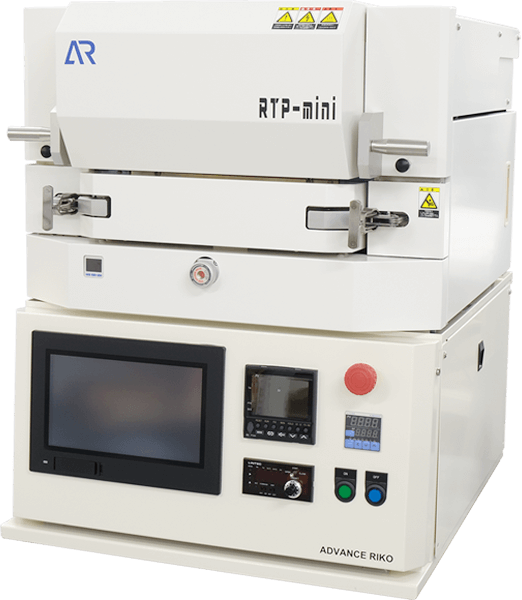
Infrared lamp heating system RTP-mini
Thermal Flow Rate Evaluation System for Low Thermal Resistance Multilayer Substrates F-CAL
Ultra High Precision Thermal Expansion Measurement System by Laser Interferometer SuperLIX
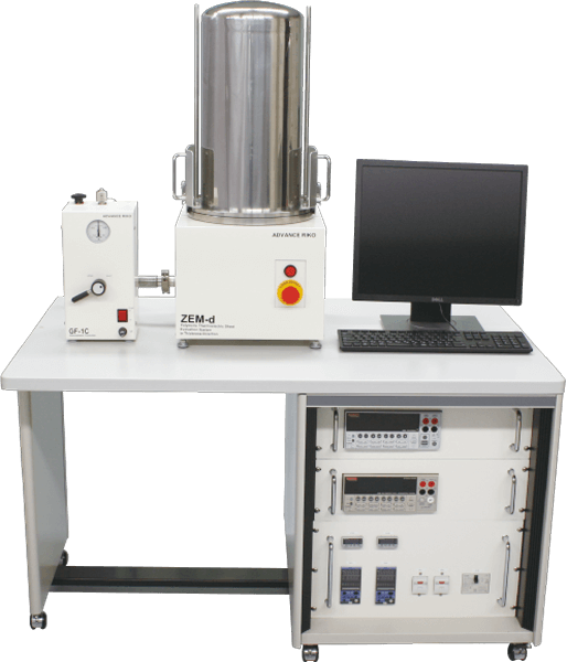
Polymeric Thermoelectric Sheet Evaluation System ZEM-d
Seebeck Coefficient / Electric Resistance Measurement System ZEM-3 series

Atmospheric Thermoelectric Module Evaluation System F-PEM
Seebeck Coefficient / Electric Resistance Measurement System ZEM-3 series Contact form
The information that you enter will only be used to provide you with a response. However, when you request that we mail you a catalog or other materials, please understand that the shipper specified by ADVANCE RIKO may use only the information necessary to send those materials, such as your name and address.
Please check our privacy policy for more details.